Step 1 · Transistors
A switch with no moving parts
Reading key: a lit dot means on, a dark one means off. A and B are the input wires. Each numbered column of a table is one possible situation, read top to bottom.
The transistor
A transistor is a switch with no moving parts. Its Control wire decides whether the other two wires are connected to each other. There are two kinds, and the small circle on the Control wire means “flipped,” the same as on a gate.
- The bar on the left is the Control plate. Its official name is the gate. In the original design it was a strip of metal.
- The gap next to it is insulation: a film of silicon dioxide — essentially glass — only a few dozen atoms thick. Nothing can flow across it.
- The line past the gap is the surface of the silicon underneath. This is where the connection happens, so it is called the channel. It is drawn broken on purpose: with the switch off, there is no path along it at all.
- The two short wires coming off the channel are the two wires being connected, called source and drain.
Those three layers, from the Control plate inward, are Metal, Oxide and Semiconductor — which is all MOS stands for. The full name is MOSFET: metal–oxide–semiconductor field-effect transistor. Modern chips have swapped in other materials for the metal and the glass, but the name stuck.
“Field effect” is the important part, because it is the whole mechanism. The Control plate never touches the channel — the glass sees to that. Instead, putting a voltage on the plate sets up an electric field across the glass, and the field pulls charges into the silicon just beneath it until they line up into a continuous path. Remove the voltage and the charges drift away and the path is gone. A switch flipped by a field through a sheet of glass: that is why it has no moving parts, and why almost no electricity flows into the Control wire itself.
Why there are two kinds: N and P
Pure silicon barely conducts. To make a transistor it is laced with a tiny amount of another element — this is called doping — and there are two ways to do it:
- Add an element like phosphorus, which brings a spare electron, and the silicon gains loose negative charges. That is n-type, for negative.
- Add an element like boron, which is one electron short, and the silicon fills with gaps where an electron should be. A gap moves around and behaves exactly like a positive charge, so this is p-type, for positive. The gaps are called holes.
The letter in front of MOS says which kind of charge forms the channel. In an NMOS the channel is made of electrons, which are negative, so they are pulled in when Control is high — on. In a PMOS the channel is made of holes, which act positive, so they are pulled in when Control is low — off. Opposite charges, opposite triggers. That is the entire reason one is the on-switch and the other is the off-switch; the little circle on the PMOS symbol is there to remind you which is which.
Pairing the two kinds so that one is always connected while the other is blocked is called CMOS — complementary MOS — and it is what every gate on the next page is built from.
Watch one flip
First, what on and off actually are. They are two voltage levels: Power's and Ground's. A wire is on when it's connected to Power and off when it's connected to Ground. Off doesn't mean empty — it means sitting at Ground's level. The Control button below works the same way: it connects the Control wire to Power or to Ground.
Below are two switches, one of each kind, so you can compare them. Each sits in its own small circuit: Power at the top, then the switch, then a lamp, then Ground. When a switch connects, electricity runs from Power through the lamp to Ground and the lamp lights. When it blocks, nothing flows and the lamp stays dark — and the wire above it is off, because through the lamp it is tied to Ground. One Control wire runs to both switches.
Exactly one lamp is lit at any moment. Flip Control and they swap: the same wire always opens one switch and closes the other. Rule: the on-switch connects when Control is on, and the off-switch connects when Control is off. Exactly one of them is connected at any moment — which is the fact every gate on the next page is built out of.
Notation
- The on-switch is called NMOS and the off-switch PMOS — N and P for the charge that forms the channel, MOS for the metal–oxide–semiconductor sandwich.
- The three wires have official names: gate (the Control wire), source and drain (the two wires that get connected).
- The transistor's “gate” wire is a different thing from a “logic gate.” Same word, unrelated meanings.
Story
The first transistor was built in 1947 at Bell Labs, the research arm of the American telephone company, by John Bardeen, Walter Brattain and William Shockley. They shared the Nobel Prize for it in 1956. It replaced the vacuum tube, a glass bulb the size of a thumb that did the same switching job but ran hot and burned out like a light bulb. The name is short for “transfer resistor.” The kind used here, the MOS transistor, came out of the same lab in 1959, invented by Mohamed Atalla and Dawon Kahng, and it is the kind inside every modern chip. The first transistor was the size of a thumb. A phone chip today holds billions.
The switch and the selector
The switch
A switch passes its signal when the control is and passes nothing when the control is . Nothing is not the same as , which is why a switch isn't a gate.
— = nothing passes
The selector
Two switches share an output, one controlled by B and one by ¬B. Exactly one is live at a time, so B picks which signal gets through. This is a selector, or in textbooks a multiplexer (“mux”).
Example: XOR from two switches and two NOTs
- Stream 1: B is the control, ¬A is the signal
- Stream 2: ¬B is the control, A is the signal
Agreement is relative to the control
- B is off: disagreement means A is on, so pass A as it is
- B is on: disagreement means A is off, so pass ¬A
In one line: XOR is “flip A if B is on.”
Step 2 · The seven gates
A few transistors, wired to follow one rule
A gate is a few transistors wired together to follow one rule. Two fixed wires appear in every build: Power, which is always on, and Ground, which is always off. A gate works by connecting its output to one or the other — never both, and never neither.
Pick a gate from the strip below — or use the arrow keys, or prev and next. Toggle A and B on it. The wires light where they carry a live signal, each transistor shows whether it is conducting or blocked, and the truth table marks the column you are standing in. Every table here is computed from the gate's own rule, not transcribed.
Step 3 · How they relate
Four gates, two flips, and De Morgan's law
The square
OR, NOR, NAND and AND are not four unrelated parts. They are one gate seen from four sides, and two moves get you between them.
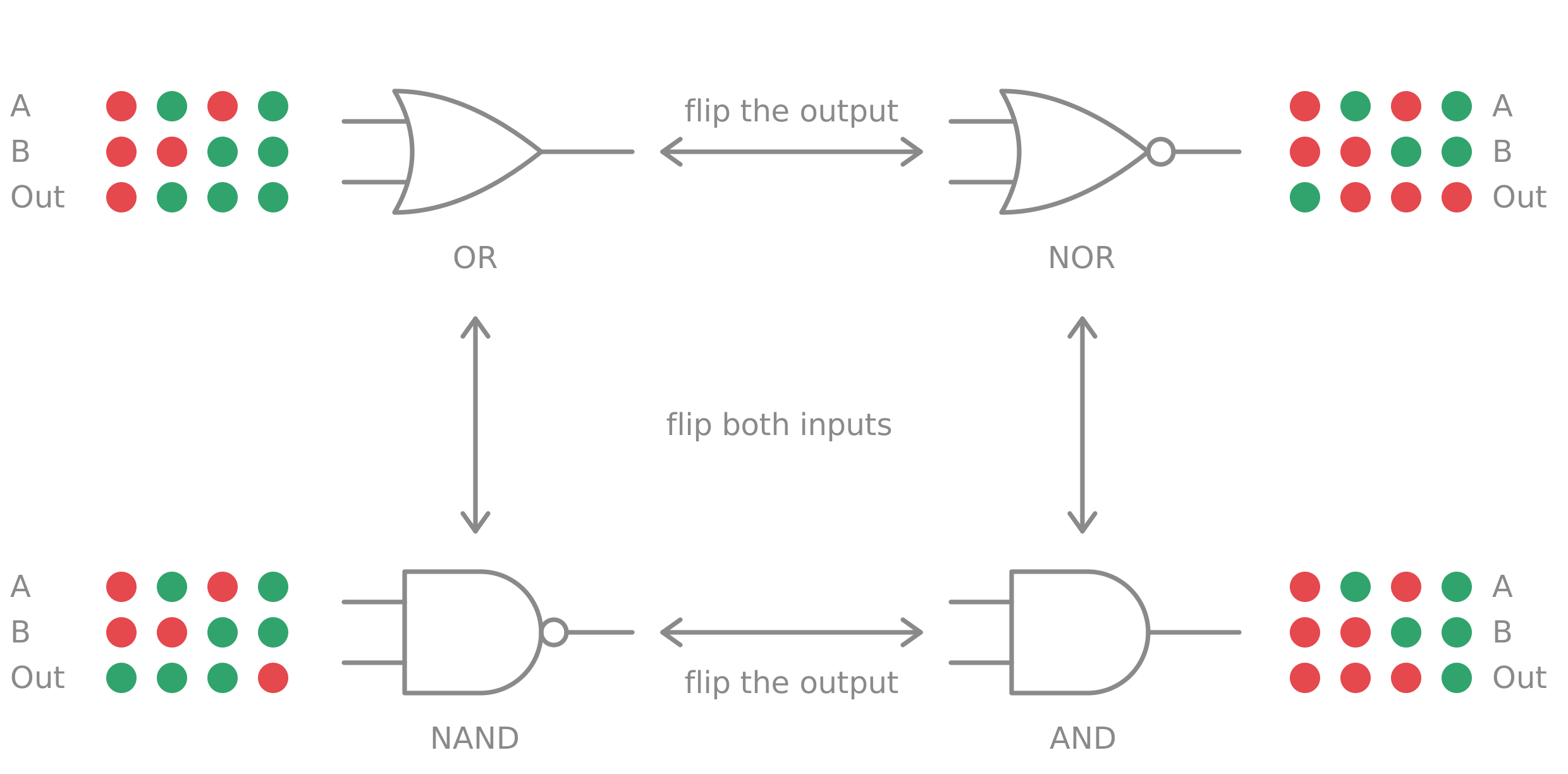
Flip the output — the sideways arrows. OR becomes NOR, and NAND becomes AND. In the table, every dot in the Out row changes colour and stays in its own column.
Flip both inputs — the up and down arrows. OR becomes NAND, and NOR becomes AND. In the table, the Out row is read backwards: column 1 trades with column 4, and column 2 trades with column 3. This happens because flipping both inputs turns “off off” into “on on” (columns 1 and 4) and “on off” into “off on” (columns 2 and 3).
De Morgan's law
The second move has a name, after Augustus De Morgan, who published it in 1847. It says a NOT on the output can be traded for a NOT on each input, as long as AND and OR trade places too. It comes in two halves:
¬(A · B)=¬A + ¬B. In words: “not both on” means the same as “at least one is off.”¬(A + B)=¬A · ¬B. In words: “neither is on” means the same as “this one is off and that one is off.”
An everyday version of the first half: “I don't have both my keys and my wallet” means “I'm missing my keys or I'm missing my wallet.”
Which gates can build all the others
NAND alone can, and NOR alone can. AND, OR and NOT cannot.
To be universal, a gate needs two abilities: a way to combine two wires into one, and a way to flip a wire. AND and OR can combine but never flip — feed either one nothing but on and the output is always on, so no matter how many you chain together, you can never turn an on into an off. NOT can flip but never combine, because it has one input. NAND and NOR are the only gates here that do both at once.
The recipes from NAND
- NOT (1 NAND): connect the same wire to both inputs. The NAND rule becomes “on unless the input is on,” which is NOT.
- AND (2 NANDs): a NAND, then a NOT to flip the output. This is the sideways arrow in the square.
- OR (3 NANDs): a NOT on each input, then a NAND. This is the up and down arrow in the square.
- NOR (4 NANDs): the OR recipe, then one more NOT.
Step 4 · Building one from others
Layers, and why XOR needs two of them
Every table below is computed from the circuit it describes, so the worked examples cannot drift from the logic they claim to show.
The words for it
- Equivalent: two circuits are equivalent when they have the same table, however different they look inside.
- Layer: the gates that sit the same number of steps from the inputs. Layer 1 reads A and B. Layer 2 reads the outputs of layer 1.
- Decomposition: breaking one job into smaller jobs that simpler gates can do. This is the name for what happens when a gate is built from others.
- Simplification: finding a smaller circuit that is equivalent to a bigger one.
Worked example 1 · XOR from an AND and two NORs
Layer 1 is an AND and a NOR, both reading A and B. Layer 2 is a NOR reading those two outputs.
AND catches “both on” and the first NOR catches “both off.” They can never fire together. The last NOR fires when neither of them fired, which leaves only the mixed situations. Swap the last NOR for an OR and the result is XNOR instead.
Worked example 2 · NOR, two ways
The goal is a circuit that fires only when both inputs are off.
Way 1 · change the inputs
“Both off” is the same as “both inverses on,” so flip each input with a NOT and feed them to an AND.
This is De Morgan's law in action. An earlier version used a NAND followed by a NOT as the last step, and simplification merges those two into the single AND.
Way 2 · catch everything else and fire on silence
Layer 1 is an AND, which catches “both on,” and an XOR, which catches “mixed.” Layer 2 is an XNOR.
AND and XOR never fire together, so the only way the XNOR's inputs can match is when both are off. That happens only when A and B are both off.
The two ways are equivalent, and each costs three gates. Way 1 changes the inputs so the wanted situation looks like one a gate already detects. Way 2 leaves the inputs alone, detects every unwanted situation, and fires when none showed up.
What a layer does to the situations
Two inputs give four situations. A layer can either relabel them or squeeze them.
- Relabeling keeps all four apart. The two NOTs in Way 1 do this. Every situation is still distinct, with the colours swapped.
- Squeezing merges some. In worked example 1, layer 1 turns four situations into three: “both off” arrives as on-off, “both on” as off-on, and the two mixed situations both arrive as off-off. Layer 2 can no longer tell which input was the lit one.
Squeezing throws away exactly the detail the final answer doesn't need. Every gate with two inputs and one output is a squeeze, since four situations become two answers. Neural networks use the same idea, and there the middle layer is called a hidden layer.
Why XOR needs two layers
Put A on one side and B on the other to get a grid:
| B off | B on | |
|---|---|---|
| A off | both off | mixed |
| A on | mixed | both on |
AND, NAND, OR and NOR each separate one corner from the other three. XOR and XNOR separate one diagonal from the other. A single simple gate can cut off a corner but not a diagonal, so XOR has to be built in two steps.
These are patterns on the grid, not moves. A pattern is which cells are lit. The moves are the flips: flipping A swaps the two rows, flipping B swaps the two columns, and flipping the output recolours every cell. The grid itself is taught under the name Karnaugh map, as a tool for simplifying by eye. The corner-versus-diagonal idea is taught in AI courses, where a pattern that one straight cut can separate is called linearly separable. XOR is the standard example of one that is not.
How XOR and XNOR pair up. Flipping the output swaps XOR and XNOR, the same way it swaps AND and NAND. Flipping both inputs of XOR gives XOR again, because its Out row reads the same backwards. Flipping only one input swaps XOR and XNOR. So XOR and XNOR do not join AND and NAND in a square. They are a pair of their own.
Step 5 · Boolean algebra
The math behind the wires
This feels different from school algebra. There, you know the function and work backwards to the input. Here, you know every input and output (the table) and build the function that connects them. Step 6, the case method, is the recipe for that, and it always works.
The closest thing here to isolating a variable is splitting on one input, in Step 6.
Boolean logic studies statements that are either true or false, joined by “and,” “or” and “not.” Here a lit dot means true and a dark one means false, and each gate is one way of joining statements. If A is “it's raining” and B is “I have an umbrella,” then “A and B” is true only when both parts are true — which is the AND table.
Where it sits in math
- Mathematical logic: the field
- Propositional logic: the part about true/false statements joined by “and,” “or” and “not”
- Boolean algebra: the same subject written as algebra, with symbols and equations. Named after George Boole.
From gates to logic
| Gate | Logic name | In these notes | Logicians write | Read as |
|---|---|---|---|---|
| NOT | negation | ¬A | ¬A | “not A” |
| AND | conjunction | A · B | A ∧ B | “A and B” |
| OR | disjunction | A + B | A ∨ B | “A or B, or both” |
| NAND | alternative denial | ¬(A · B) | A ↑ B | “not both” |
| NOR | joint denial | ¬(A + B) | A ↓ B | “neither” |
| XNOR | equivalence | A·B + ¬A·¬B | A ↔ B | “A if and only if B” |
| XOR | exclusive or | A·¬B + ¬A·B | A ⊕ B | “A or B, but not both” |
OR versus AND, and matching versus agreement
OR means at least one is true, so “or both” says the both-true case is allowed. AND means both must be true, so the both-true case is required. Everyday “or” has two meanings, which is why logic spells it out. In “a student or a senior gets the discount,” someone who is both still gets it — that is OR. In “soup or salad,” you can't have both — that is XOR.
Matching is a claim about the values themselves: AND asks “are both on?” and
NOR asks “are both off?” Agreement is a claim about how the two compare:
XNOR asks “are they the same?” whatever the colour. That makes XNOR the logic version of an
equals sign, A = B, and XOR the version of A ≠ B.
Only XOR and XNOR are pure agreement gates. The test is that their Out rows read the same
backwards. Agreement can be built from matching: A ↔ B is the same as
A·B + ¬A·¬B, meaning “both on, or both off.”
The laws
These are the rules for rewriting one formula into an equivalent one. Each comes in an AND
version and an OR version. · means AND, + means OR, ¬
means NOT, 1 is on and 0 is off. With no brackets, AND is done
before OR, the same way multiplication is done before addition.
| Law | AND version | OR version | In words |
|---|---|---|---|
| Identity | A · 1 = A | A + 0 = A | Combining with a wire that never matters changes nothing |
| Domination | A · 0 = 0 | A + 1 = 1 | One fixed wire can decide the answer alone |
| Repeat | A · A = A | A + A = A | Using the same wire twice adds nothing |
| Opposites | A · ¬A = 0 | A + ¬A = 1 | A wire and its flip are never both on, and one of them always is |
| Order | A · B = B · A | A + B = B + A | Swapping the inputs changes nothing |
| Grouping | (A·B)·C = A·(B·C) | (A+B)+C = A+(B+C) | With three inputs, it doesn't matter which two go first |
| Sharing | A·(B + C) = A·B + A·C | A + B·C = (A+B)·(A+C) | A shared wire can be pulled out or pushed in |
| Absorption | A·(A + B) = A | A + A·B = A | If A already decides it, the extra part is wasted |
| De Morgan | ¬(A·B) = ¬A + ¬B | ¬(A+B) = ¬A·¬B | Move a NOT to the inputs and AND and OR trade places |
One more law has no partner: ¬¬A = A. Flipping twice gets you back where you
started.
The two versions of each law are mirror images. Take either one, swap every ·
with + and every 0 with 1, and you get the other. That mirror is called
duality. Textbooks use other names for some of these: Repeat is
“idempotent,” Opposites is “complement,” Order is “commutative,” Grouping is “associative,”
and Sharing is “distributive.”
The Opposites law, up close
A wire and its flip are never both on. So any piece of a formula that asks for both describes a situation that cannot happen, and it is worth 0. This is the law that makes formulas shrink. When two brackets are multiplied out, some pieces turn out to be impossible and vanish:
(¬A + ¬B) · (A + B)= ¬A·A + ¬A·B + ¬B·A + ¬B·B- The first piece asks for A off and A on. The last asks for B off and B on. Both are impossible.
= 0 + ¬A·B + A·¬B + 0= A·¬B + ¬A·B
Four pieces went in and only the two possible ones survived. The OR half works the other way:
in A·B + A·¬B = A·(B + ¬B) = A, the bracket B + ¬B is always true,
which means B never mattered. It is also the formula behind “they never overlap.” Two
detectors are mutually exclusive when ANDing them gives 0 — for the AND and NOR in the XOR
build, (A·B) · (¬A·¬B) contains both A and ¬A, so it
is 0.
The arithmetic reading
Treat off as 0 and on as 1, and two gates turn into ordinary arithmetic. AND is multiplication: 1 × 1 = 1, and anything × 0 = 0. XOR is addition that keeps only odd or even: 1 + 1 = 2, which is even, so it becomes 0.
Step 6 · The case method
Any table at all, turned into a circuit
Simplification
Simplifying means finding a smaller circuit equivalent to the one you have. Fewer gates means a chip that is cheaper, faster and uses less power, so real chip design spends a great deal of effort on it.
A double flip
¬(¬(A · B))= A · B, because flipping twice changes nothing
Two gates become one AND.
Merging cases
Suppose a circuit should fire when “A is on and B is on” or when “A is on and B is off”:
A·B + A·¬B= A·(B + ¬B), by Sharing, pulling out the A= A·1, by Opposites= A, by Identity
The two cases differed only in B, so B never mattered. Three gates become a plain wire.
Two spellings of XOR
The XOR circuit from Step 4, rewritten into the textbook form:
¬(A·B + ¬(A + B))= ¬(A·B) · ¬¬(A + B), by De Morgan on the outer NOT= ¬(A·B) · (A + B), because flipping twice changes nothing= (¬A + ¬B) · (A + B), by De Morgan on the first bracket= ¬A·A + ¬A·B + ¬B·A + ¬B·B, by Sharing= 0 + ¬A·B + A·¬B + 0, by Opposites= A·¬B + ¬A·B, by Identity
The third line is worth reading on its own: “not both on, and at least one on.” That is a third way of saying “they disagree.”
The recipe
This turns any table of dots into a circuit.
- Pick the columns that should be on. Each one is a case.
- Build one detector per case. A detector fires in exactly one column and stays off in the others.
- OR the detectors together.
- Simplify the result with the laws.
The four detectors
| Case | Detector | As a gate |
|---|---|---|
| Both off | ¬A · ¬B | NOR |
| A on, B off | A · ¬B | AND with a NOT on B |
| A off, B on | ¬A · B | AND with a NOT on A |
| Both on | A · B | AND |
The textbook name for one of these detectors is a minterm. Each fires in exactly one column, and the inputs can only be in one column at a time, so no two detectors can fire together — they are mutually exclusive. That is why step 3 can always use a plain OR: its “both inputs on” case never comes up.
Example · fire when the inputs agree
- The on cases are “both on” and “both off”
- The detectors are AND and NOR
- OR them together:
A·B + ¬A·¬B
That formula is XNOR.
The mirror version. When most columns should be on, it is less work to detect the off cases and flip the answer at the end, so the circuit fires when no detector did. The XOR build in Step 2 does exactly this.
Engineers call the result a sum of products, because it is an OR of ANDs. Logicians call it disjunctive normal form. It always works, for any table and any number of inputs — a theorem, and the reason NAND is universal, since NOT, AND and OR are enough to write any table and NAND can make all three.
The Shannon expansion: splitting on one input
This is a second way to turn a table into a circuit, and it's the closest thing here to isolating a variable in school algebra. Pick one input and split the table into the cases where it's off and the cases where it's on. Each half is a smaller table with one input fewer, so a 16-case puzzle with four inputs becomes two 8-case puzzles. If a half is still hard, you split it again. With only two inputs you can read the answer straight off the table, so the payoff comes with bigger puzzles.
- Pick an input to split on, for example B.
- Work out what Out is when B is off, using only the other inputs.
- Work out what Out is when B is on.
- Put a selector on B (Step 1). The “B off” answer goes through the ¬B switch, and the “B on” answer goes through the B switch.
For XOR, the cases where B is off are columns 1 and 2, and there Out matches A. In columns 3 and 4,
where B is on, Out is the opposite of A. So A ⊕ B = ¬B·A + B·¬A, where
B · something reads as “something, but only when B is on.” That's the selector from
Step 1.
Claude Shannon used this for switch circuits in the 1940s, but George Boole wrote it down first, in 1854, so it's also called Boole's expansion theorem.
Every symbol, with its other spellings
| Meaning | Here | Also written |
|---|---|---|
| NOT A | ¬A | A with a bar over it, A′, ~A, !A |
| A AND B | A · B | AB, A ∧ B |
| A OR B | A + B | A ∨ B |
| A NAND B | ¬(A · B) | A ↑ B, the Sheffer stroke |
| A NOR B | ¬(A + B) | A ↓ B, the Peirce arrow |
| A XOR B | A ⊕ B | A ≠ B, A ⊻ B |
| A XNOR B | ¬(A ⊕ B) | A ⊙ B, A ↔ B, A = B |
| Always on | 1 | true |
| Always off | 0 | false |
Step 7 · Binary
Counting with switches
A wire is on or off, so a row of wires can only spell numbers in twos. Each place is worth double the one to its right, and a number is just the sum of the places that are lit. Switch some on.
Eight places
Why each number has exactly one spelling
Decimal lets you write the same quantity several ways if you cheat — 0.9999… and
1 are the same number. Binary has no such slack: every whole number has exactly
one spelling, and the reason is that you are never given a choice.
Look at the last digit. It is worth 1, and every other place is worth an even number — 2, 4, 8, 16, all of them multiples of two. So the lit places other than the last always add up to something even. That means the last digit alone decides whether the total is odd or even, and it is forced: 1 if the number is odd, 0 if it is even. There is no second option.
Now take that digit off and halve what's left. You are looking at a smaller number with the same question, and its last digit is forced for the same reason. Keep going and you reach zero. Every digit along the way was decided for you, so the spelling you end up with is the only one there was. The table above the readout does this live for whatever number is currently switched on.
Said the other way round, which is how you put it: every even number is some combination of powers of two, and every odd number is that same combination plus one. The “plus one” is the last digit, and it has nowhere else to go.
All ones, and why a byte stops at 255
Press fill every place above. Eight lit places give 255, which is
28 − 1 — one short of the next power of two. That is not a
coincidence about 8. For any n:
1 + 2 + 4 + … + 2n−1 = 2n − 1
Every power of two is built out of all the smaller ones, plus one. Stack every place you have
and you land exactly one short of the next place up — 0111 is one less than
1000.
The quickest way to see it is to add 1 to a row of ones and watch the carry run. Each 1 becomes 0 and passes a carry along, the whole row empties, and a single new place lights at the far end. Nothing is left over, which is only possible if the row of ones was worth exactly one less than that new place.
This is why counts in computing stop where they do. n bits give you
2n different patterns, and since one of them is zero, the largest
number is 2n − 1. A byte runs 0 to 255, not 0 to 256. Two bytes reach
65,535. It is also why the lit places in the strip above are never ambiguous: each one
contributes more than everything to its right put together, so no combination of smaller
places can ever stand in for a bigger one.
Where the gates come back in
Add two single bits and there are only four sums: 0+0, 0+1, 1+0 and 1+1. The first three are
0, 1 and 1. The last is 2, which in binary is 10 — a 0 in this column and a carry
into the next.
So the answer needs two wires, and each is a gate you already have. The sum digit is on when the inputs disagree, which is XOR. The carry is on only when both are on, which is AND. Two gates, side by side, reading the same pair of wires:
This is called a half adder — half, because it produces a carry but has nowhere to accept one coming in from the column to its right. Give it a third input for that and it becomes a full adder; chain eight full adders together and you have something that adds bytes. That chain is inside every processor, and it is built from the parts on this page.